
Laser Line Uniformity Projection Geometry in Optical Metrology Systems
Technical Depth
White Paper
Laser Line Uniformity Projection Geometry in Optical Metrology Systems
White Paper | Diode Laser Concepts
1. Introduction
When specifying a laser line module, it is important for OEM system designers to recognize that perceived laser line uniformity depends strongly on how it is measured and where it is evaluated within the application. A laser line that appears highly uniform under one measurement method may exhibit noticeable variation under another. Factors such as working distance, projection angle, target geometry, and metrology approach can significantly influence observed performance. Understanding these effects is essential when defining laser line uniformity requirements for machine vision, triangulation, and precision optical inspection systems to ensure specifications align with real-world system expectations and avoid unnecessary design constraints.
2. Technical Background
A laser line that appears perfectly uniform when measured radially (constant radial distance from the laser module) may be expected to project with the same uniformity onto a flat plane. However, this assumption overlooks an important geometric effect associated with projection angle. The rotating detector positioned at a constant radial distance measures the optical power distribution in angular space, whereas a flat target samples irradiance across a linear distance. Because equal angular increments correspond to increasingly larger physical distances away from the optical axis, a laser line exhibiting uniform radial irradiance will naturally appear non-uniform when projected onto a planar surface.
3. Geometric Projections
The geometries below compare two common methods for evaluating laser line uniformity: an angular measurement surface at constant radial distance from the emission point and a flat target plane orthogonal to the optical axis. The relationship between these measurement approaches is governed by conservation of optical power, where the energy contained within a small angular segment must equal the energy distributed across the corresponding linear segment on the planar surface.
We begin with a radial projection surface located on a circular arc whose radius equals the perpendicular working distance to a planar projection surface and the following trigonometric relation:
\[
x = R\tan(\theta)
\]
Where:
• R denotes the working distance from the source to the planar surface and radius of radial surface.
• θ denotes the angular position relative to the optical axis.
• x denotes the linear position on the planar surface.
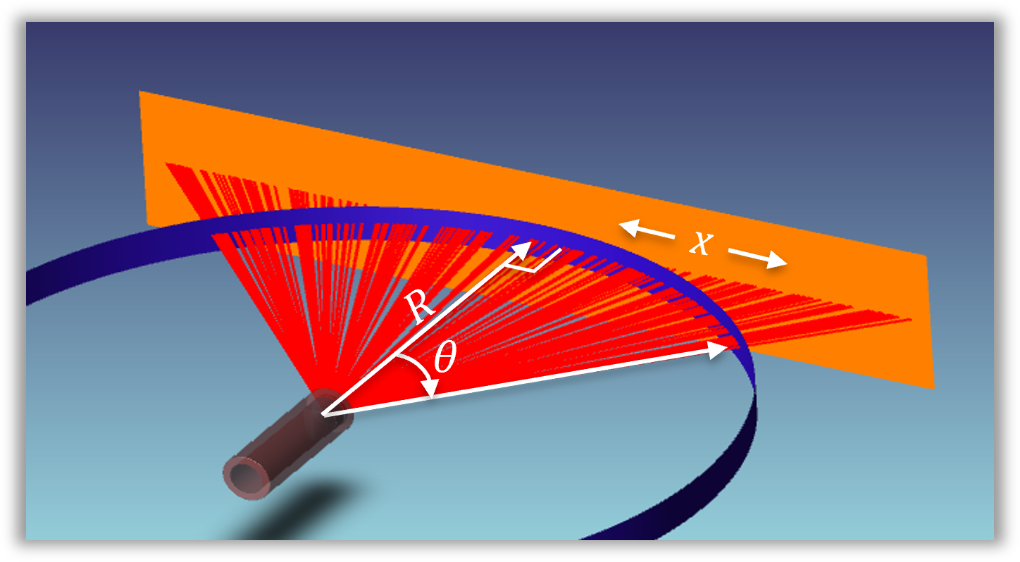
Layout of projection geometries.
Taking the derivative:
\[
\frac{dx}{d\theta} = R\sec^2(\theta)
\]
Thus:
\[
dx = R\sec^2(\theta)\,d\theta
\]
Think of this as the geometric stretching term. Equal angular increments occupy increasingly larger linear distances at larger projection angles.
Next, we apply conservation of optical power treating the laser line as essentially one-dimensional.
Defining the irradiance measured radially as:
\[
I_r(\theta)
\]
An infinitesimal arc length at radius R is:
\[
ds = R\,d\theta
\]
The optical power equals irradiance times arc length, so the power contained in a small angular segment is:
\[
dP = I_r(\theta)\,R\,d\theta
\]
On the flat target plane, we define linear irradiance as:
\[
I_L(x)
\]
The same optical power must occupy the linear segment:
\[
dx
\]
Setting the angular and linear optical powers equal:
\[
dP = I_L(x)\,dx
\]
Thus:
\[
I_r(\theta)\,R\,d\theta = I_L(x)\,dx
\]
Substituting from our previous projection geometry result:
\[
dx = R\sec^2(\theta)\,d\theta
\]
Gives:
\[
I_r(\theta)\,R\,d\theta = I_L(x)\,R\sec^2(\theta)\,d\theta
\]
Cancelling R and dθ:
\[
I_r(\theta) = I_L(x)\sec^2(\theta)
\]
Rearranging yields the governing relationship:
\[
I_L(x) = I_r(\theta)\cos^2(\theta)
\]
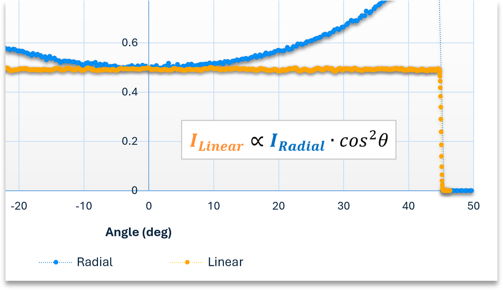
Thus, a uniform flattop power distribution projected on an orthogonal flat plane will result in a nonuniform edge-brightened distribution when measured radially, following this \( \cos^2(\theta) \) transformation.
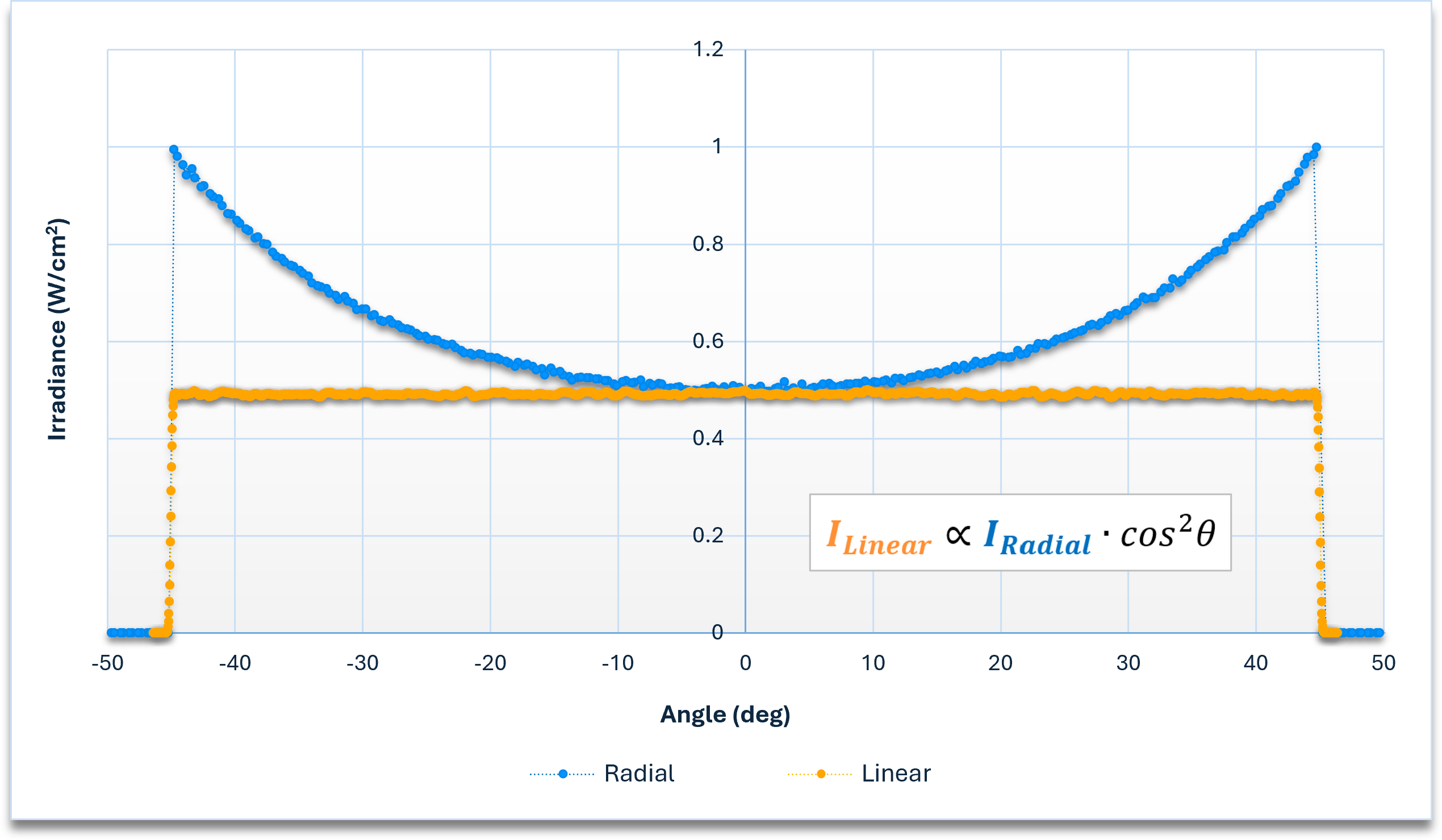
Laser line data aligned for uniform irradiance on an orthogonal flat plane. Data normalized to maximum radial value.
Likewise, a uniform laser line in angular space transforms to an edge-dimmed distribution on a planar target.
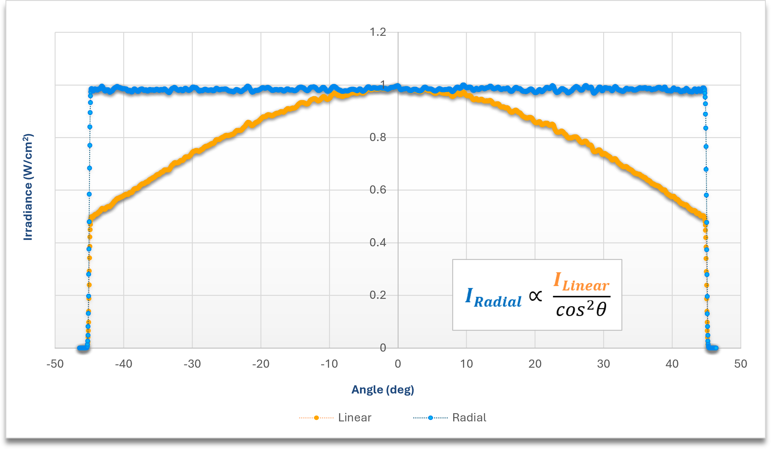
Laser line data aligned for uniform angular power distribution. Data normalized to maximum linear value.
4. Applications
When manufacturing laser line sources designed to comply with CDRH and IEC laser classification requirements, manufacturers must ensure optical power remains below specified limits when evaluated using standardized radial measurement methodologies. As a result, laser line uniformity metrology during optical alignment is often performed at a constant radial distance from the emission point. In many end-use applications—particularly machine vision, triangulation, and optical inspection systems—customers instead evaluate the laser line as projected onto a flat target plane and often expect a uniform linear intensity distribution. To achieve this outcome, manufacturers must account for the geometric transformation described above and intentionally design an edge-brightened angular power distribution such that the projected line appears uniform on a planar surface. Understanding the relationship between measurement geometry and perceived irradiance distribution is therefore essential for establishing meaningful performance specifications and accurately predicting real-world system behavior.
5. Practical Considerations
In many real-world machine vision and metrology applications, laser line uniformity is evaluated using a camera imaging light scattered from a diffuse target surface rather than by directly measuring irradiance at the target plane. In this case, the captured image represents the scattered response of the projected irradiance distribution and may also be influenced by target reflectivity, viewing angle, camera optics, exposure settings, and sensor response. However, for a diffuse target under controlled imaging conditions, the measured camera intensity profile is generally proportional to the irradiance distribution incident on the target surface. As a result, the geometric relationship derived above provides a practical and accurate framework for understanding how a radially uniform laser line will appear in a camera-based planar measurement system.
Note: Throughout this analysis, the laser line is modeled as a one-dimensional irradiance distribution. The finite line width is assumed constant, allowing the derivation to isolate the geometric transformation governing irradiance variation along the length of the projected laser line. For simplicity, we use “power distribution” and “irradiance distribution” interchangeably when discussing laser line uniformity.
For additional information regarding laser line metrology, custom laser line generators, or application-specific optical design support, contact DLC at [email protected] or submit an inquiry via the Contact Form on our website.
Diode Laser Concepts, Inc.
Website: www.diodelaserconcepts.com
Email: [email protected]
Phone: 541-773-5321