
Laser Line Width Characterization, Propagation and Fan Angle
Technical Depth
White Paper
Laser Line Width Characterization, Propagation and Fan Angle
White Paper | Diode Laser Concepts
1. Introduction
Laser line sources are widely used in machine vision, 3D scanning, metrology, inspection, and alignment applications where the projected line serves as a precise optical reference or analysis tool. One of the primary specifications defining a laser line source is its line thickness cross-section or width, and in many cases, the initial desire is simply “the thinnest line possible.”
While a thin line can improve measurement resolution and edge definition, line width cannot be considered independently of the application’s operating conditions. A laser line is a focused optical beam whose thickness changes continuously as it propagates. A line that is exceptionally thin at one working distance may become significantly wider only a short distance away, while a slightly thicker line may provide more consistent performance over the full operating range. Optimizing the width characteristics for the complete application—not just one operating point—often produces the best overall system performance.
The intent of this paper is to provide a practical guide for system designers and application engineers working with laser line sources. Rather than presenting a rigorous treatment of optical theory, the discussion focuses on the fundamental principles governing laser line width behavior, practical design considerations, and their impact on real-world applications.
2. Defining Laser Line Width
A laser line is generated by expanding a laser beam in one dimension using various optical elements. When focused appropriately, the projected output on a far-field plane appears as a thin line. Its width is defined by the intensity distribution measured across a cross-section perpendicular to the line. Understanding this cross-section is fundamental to understanding how line width is specified and how it changes with propagation distance.
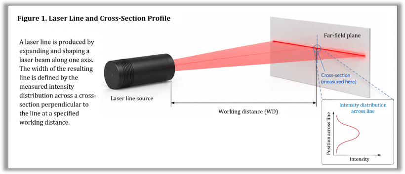
Representation of a laser line projected onto a far-field plane. For a given point along the line, the cross-sectional intensity distribution is measured perpendicular to the line orientation.
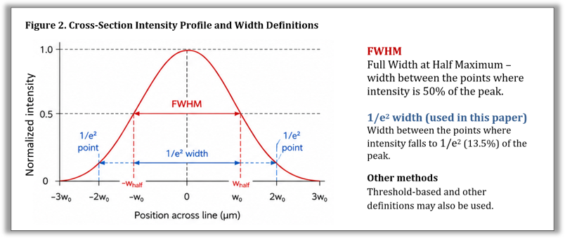
Idealized Gaussian profile illustrating common beam width definitions. Actual laser line width cross-section profiles often deviate from an ideal Gaussian distribution due to diode characteristics, optical design, aberrations, and manufacturing tolerances.
An ideal laser beam exhibits a Gaussian intensity distribution, with the highest optical intensity at the center of the beam and a gradual decrease toward the edges. Because the beam does not have a sharply defined edge, its width must be specified using a defined measurement criterion. Common definitions include the 1/e² width, the full width at half maximum (FWHM), and application-specific threshold methods. Throughout this paper, the 1/e² width will be used as it is the standard convention for describing Gaussian beam propagation.
3. Gaussian Propagation of a Laser Line
Typical laser line applications require a “focused line”. As the line propagates away from the source, its cross-sectional width converges (narrows) to a minimum before gradually diverging (expanding) again. In this paper, this minima location is referred to as the minimum line width location or beam waist (ideal Gaussian).
Although real-world laser line sources are influenced by factors such as beam quality (M^2), optical aberrations, manufacturing tolerances, wavelength, and the specific method used to measure line width, Gaussian beam propagation theory provides an excellent first-order model for understanding how line width varies with propagation distance. It captures the fundamental behavior of a focused laser beam while providing sufficient accuracy for most practical engineering applications.
In this section, we introduce the basic principles of Gaussian beam propagation as they apply to laser line width. To maintain the practical focus and limited scope of this paper, our discussion emphasizes the relationships most relevant to system designers and application engineers. More advanced topics related to optical design and beam propagation have been intentionally simplified or omitted, as they do not materially affect the scope of this paper.
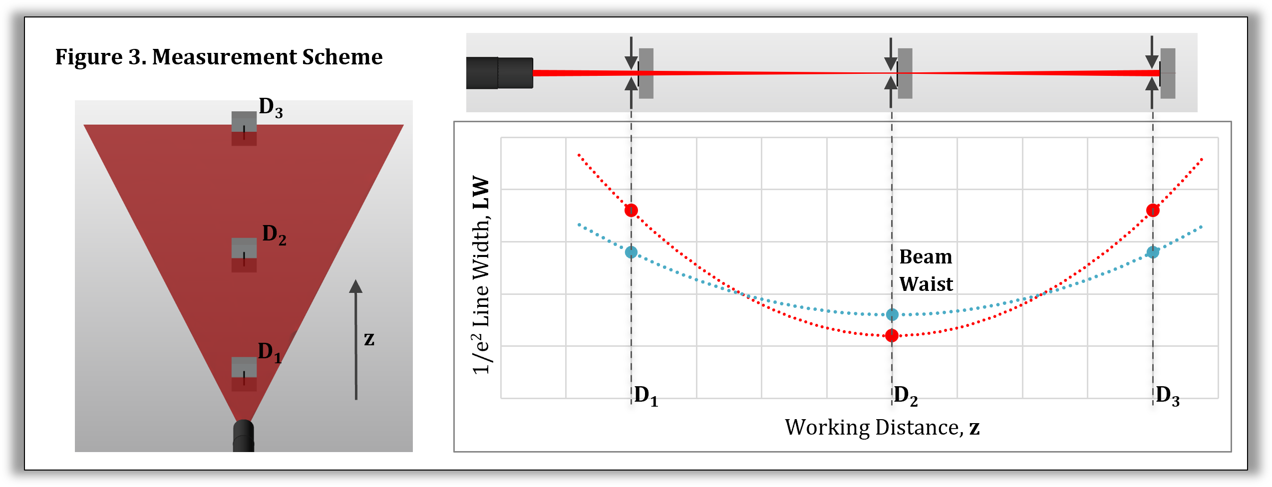
Representation of a 3-distance line width measurement scheme. Line width (LW) measured and plotted at z distances (D₁, D₂, D₃). Minimum width located at D₂. For an ideal Gaussian beam, the minimum line width and beam waist are used interchangeably.
For an ideal Gaussian beam, the line width LW at any propagation distance z can be described by
$$
LW(z) = LW_0 \sqrt{1 + \left(\frac{z-z_0}{z_R}\right)^2}
$$
LW(z) = LW_0 \sqrt{1 + \left(\frac{z-z_0}{z_R}\right)^2}
$$
Note: For convenience, the Gaussian propagation equation is expressed in terms of working distance from the laser module.
where:
• LW0 = minimum 1/e² line width
• z = working distance measured from the laser module reference surface
• z0 = working distance at which the laser line reaches its minimum 1/e² width
• zR = Rayleigh range: the distance over which the beam width (or line width in this case) remains relatively close to its minimum width LW0 before divergence becomes more significant
The Rayleigh range, zR determines how rapidly the line width changes as the beam propagates. A longer Rayleigh range results in a more gradual change in line width (blue plot), while a shorter Rayleigh range produces a tighter focus with more rapid divergence (red plot).
The minimum line width, LW0, is established by the optical design of the laser module and occurs at the beam waist. It is influenced by several factors, including the input beam characteristics, wavelength, beam quality, focusing optics, working distance, and optical aberrations. Determining the theoretical minimum line width is beyond the scope of this paper; instead, LW0 is treated as the starting point from which the variation in line width with working distance can be predicted using Gaussian beam propagation.
An important relationship to note is the more tightly focused the waist is at a particular working distance, the faster the line width changes outside this particular location. Often times, a design compromise is necessary where minimum width at the waist is sacrificed in order to maintain more reasonable values over a wider range.
4. Line Width Uniformity Across the Projected Line
In the previous section, the change in laser line width was described as a function of working distance along the optical axis. A similar effect occurs across the length of the projected laser line due to the geometry of the emission fan angle. Although the laser module may be focused at the center of the projected line, where the beam travels the shortest distance to the target, points farther from the center of the line experience a longer optical path before reaching the same target plane.
Consider a laser line projected onto a flat orthogonal surface. At the center of the line (0° fan angle), the beam travels the shortest distance from the laser module to the target, corresponding to the nominal working distance and the location of minimum line width. As the projection angle increases toward the edges of the line, the beam travels a longer path before reaching the target surface.
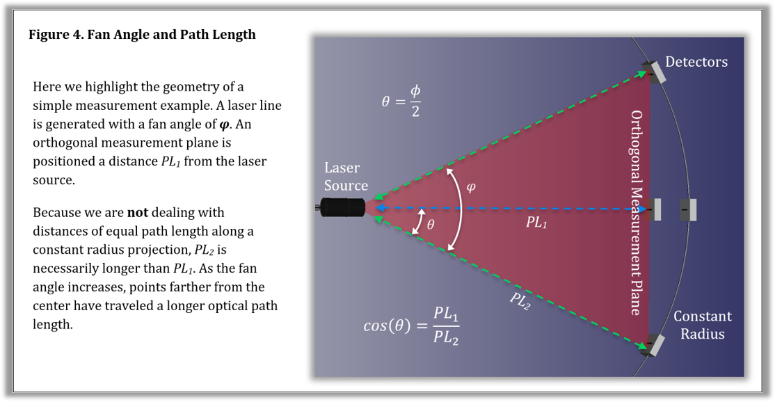
Geometry and trigonometry of laser line fan envelope incident onto an orthogonal flat measurement plane.
The increased propagation distance experienced by laser light emitted at angles away from the optical axis causes the beam to expand according to the same Gaussian beam propagation principles discussed previously. The laser line width may be minimized where the optical path length is shortest, but points farther from the center of the line propagate a greater distance before reaching the target plane. As a result, the line width gradually increases toward the edges of the projected line. This variation can be approximated by considering the change in propagation distance introduced by the fan angle geometry.
For a point located at an angle θ from the center axis of the line, the effective path length is increased by a factor of \( 1/cos(\theta) \). Therefore, the line width at any point along the fan can be approximated as:
$$
LW(\theta) = \frac{LW_{\mathrm{center}}}{\cos(\theta)}
$$
where:
• LW(θ) is the line width at an angular position θ from the center of the projected line
• LWcenter is the minimum line width at the center of the line
• θ is the angle from the optical axis
At the edge of the projected line, θ is equal to half of the full fan angle:
$$
\theta = \frac{\phi}{2}
$$
giving:
$$
LW_{\mathrm{edge}} = \frac{LW_{\mathrm{center}}}{\cos\left(\frac{\phi}{2}\right)}
$$
where φ is the total fan angle.
Therefore, even when the laser line is perfectly focused at the center, the line width will gradually increase toward the ends of the projected line. This effect becomes more pronounced as the fan angle increases because larger angles create a greater difference in path length between the center and the edges of the line.
Normalizing the center line width LWcenter to a value of 1, we can expect the following line width behavior for increasing fan angle.
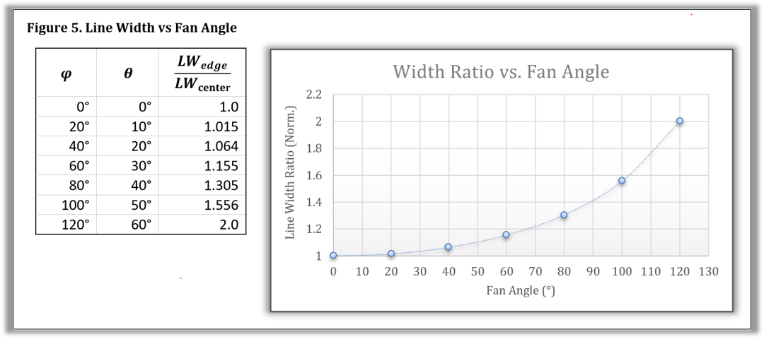
Line width growth for increasing fan angle relative to the line center width. Values are idealized and do not consider other real-world effects that can impact line width growth with angle.
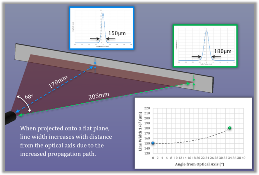
To further emphasize this behavior, let’s consider a specific use-case example with a laser module designed with the following specifications:
• Fan angle – 68°
• Focused waist location – 170mm
• Minimum 1/e² line width at waist – 150µm
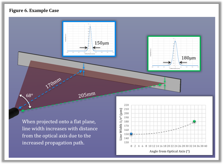
Representation of real-world impact on line width. Presented values are for a specific case and do not apply generally.
5. Summary
Line width should not be treated as a single specification, but rather as a characteristic that varies with both working distance and position along the projected line. By considering these factors during the design process, system designers can make informed tradeoffs and specify a laser source that delivers consistent, reliable results under real operating conditions within their application.
For additional information regarding laser line metrology, custom laser line generators, or application-specific optical design support, contact DLC at [email protected] or submit an inquiry via the Contact Form on our website.
Diode Laser Concepts, Inc.
Website: www.diodelaserconcepts.com
Email: [email protected]
Phone: 541-773-5321